Home / Resources / Machine Videos and Factory Photos
Deep-Hole Machine Videos and Factory Photos
Review real machine layouts, work zones, tooling, coolant and chip-handling systems before discussing a model. This media library is organized by what the camera proves—not by unsupported performance claims.
Evidence boundary: photographs and videos confirm visible equipment and workshop context only. They do not prove a model number, order, shipment, installation, cycle time, dimensional result or customer acceptance unless a separate verified record is linked.
Featured Machine Video
Gun drilling
Enclosed deep-hole machine walkaround
A short visual walkaround showing the enclosure, CNC control, spindle area and internal supports.
Silent web edition. Final machine selection and acceptance limits are defined from the workpiece drawing and signed technical agreement.
Process and Machine-System Videos
Multi-station gun drilling
Dual-spindle layout, control and work zone
Operator-side view of the control station followed by the dual-spindle work zone and tool-support arrangement.
Silent web edition. Final machine selection and acceptance limits are defined from the workpiece drawing and signed technical agreement.
Large-bore machining
Large cylindrical workpiece internal machining
Workshop footage of a large cylindrical workpiece during internal machining. The visual does not define the final process route or acceptance result.
Silent web edition. Final machine selection and acceptance limits are defined from the workpiece drawing and signed technical agreement.
Inspection context
Machined bore surface visual inspection
Close visual inspection of a machined cylindrical bore. Surface finish and geometry require instrumented inspection and are not inferred from appearance.
Silent web edition. Final machine selection and acceptance limits are defined from the workpiece drawing and signed technical agreement.
Factory build
Coolant and chip-handling walkaround
Rear-side machine walkaround showing pumps, coolant circulation and chip-collection equipment.
Silent web edition. Final machine selection and acceptance limits are defined from the workpiece drawing and signed technical agreement.
Machine, Tooling and Factory Photo Library
Tooling
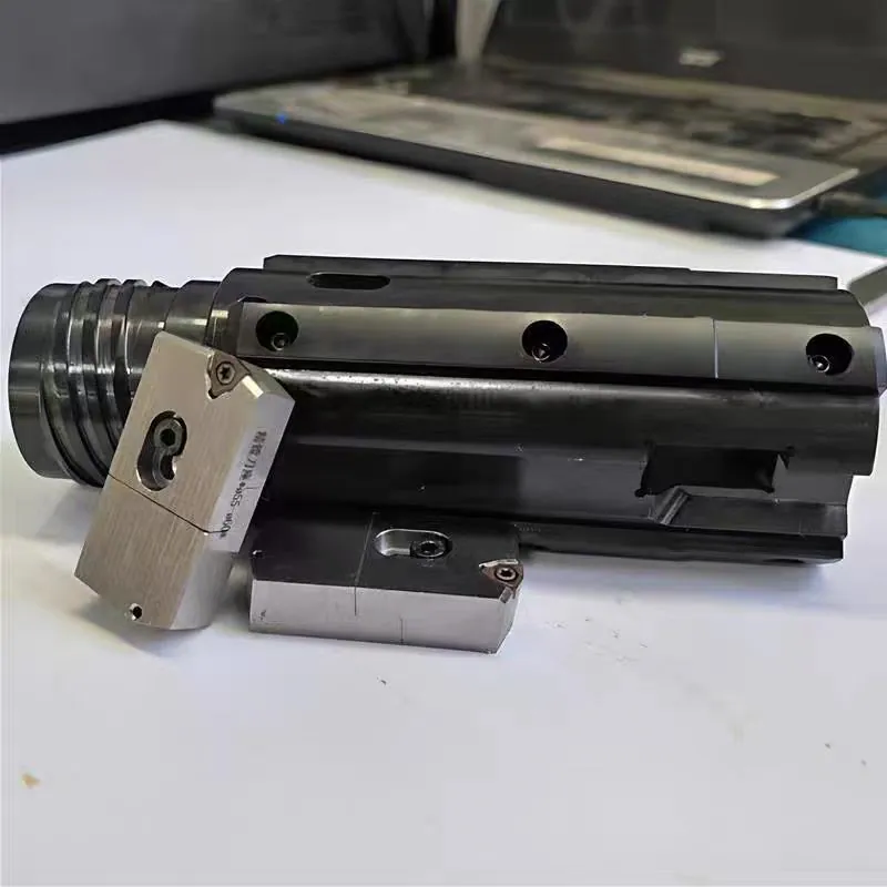
Deep-hole machining tool assembly
A close-up tool assembly for engineering discussion. Final tooling depends on the bore, material, allowance and process route.
Gun drilling
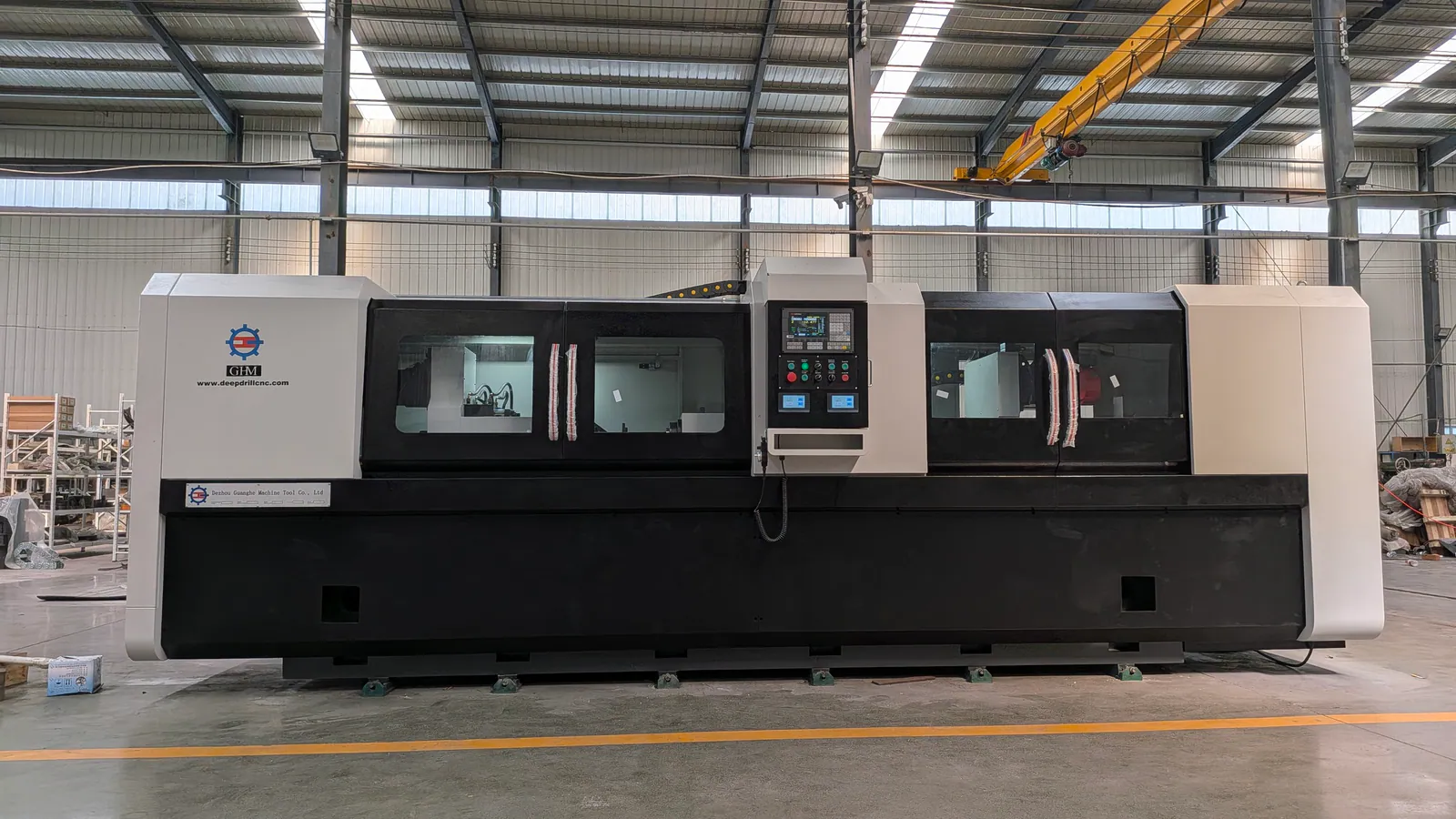
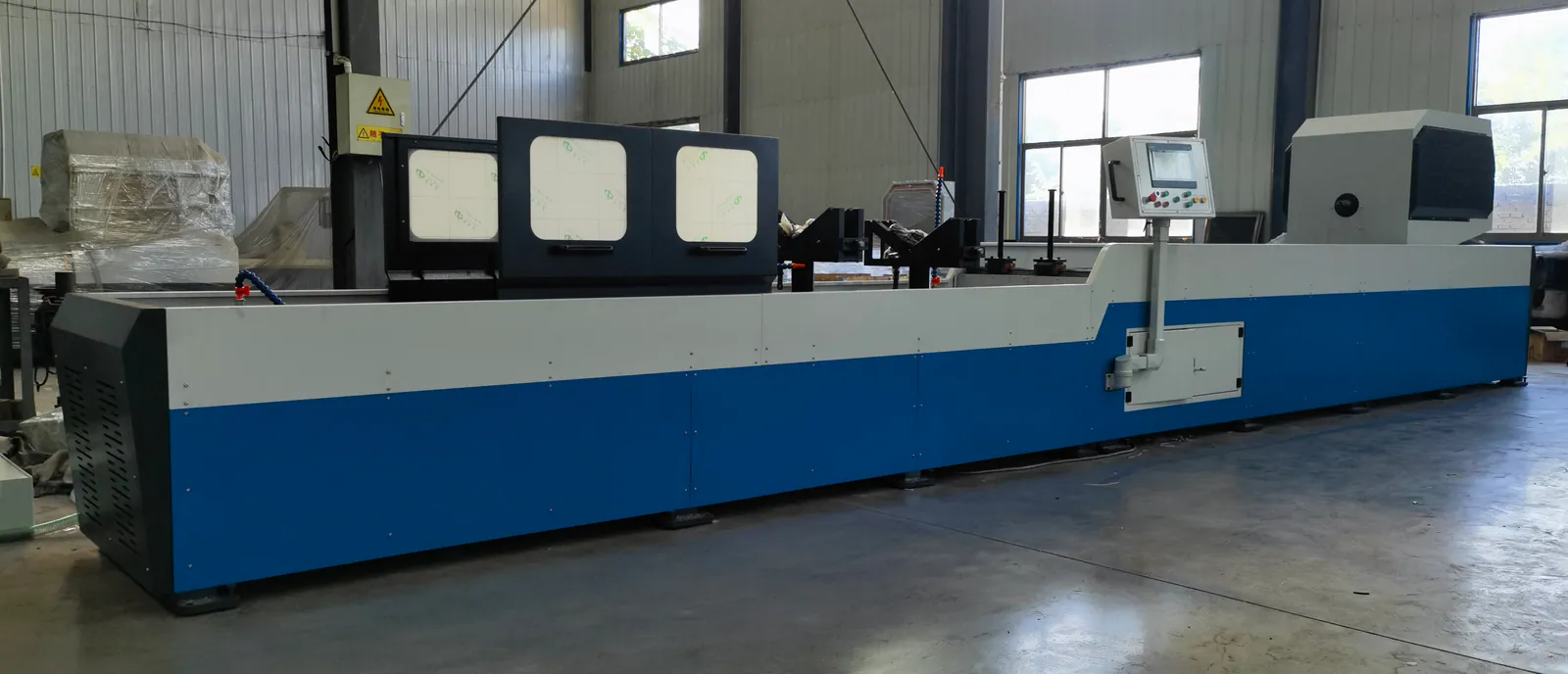
Enclosed dual-spindle deep-hole machine
Front workshop view showing the enclosure, control station and dual processing layout.
Gun drilling
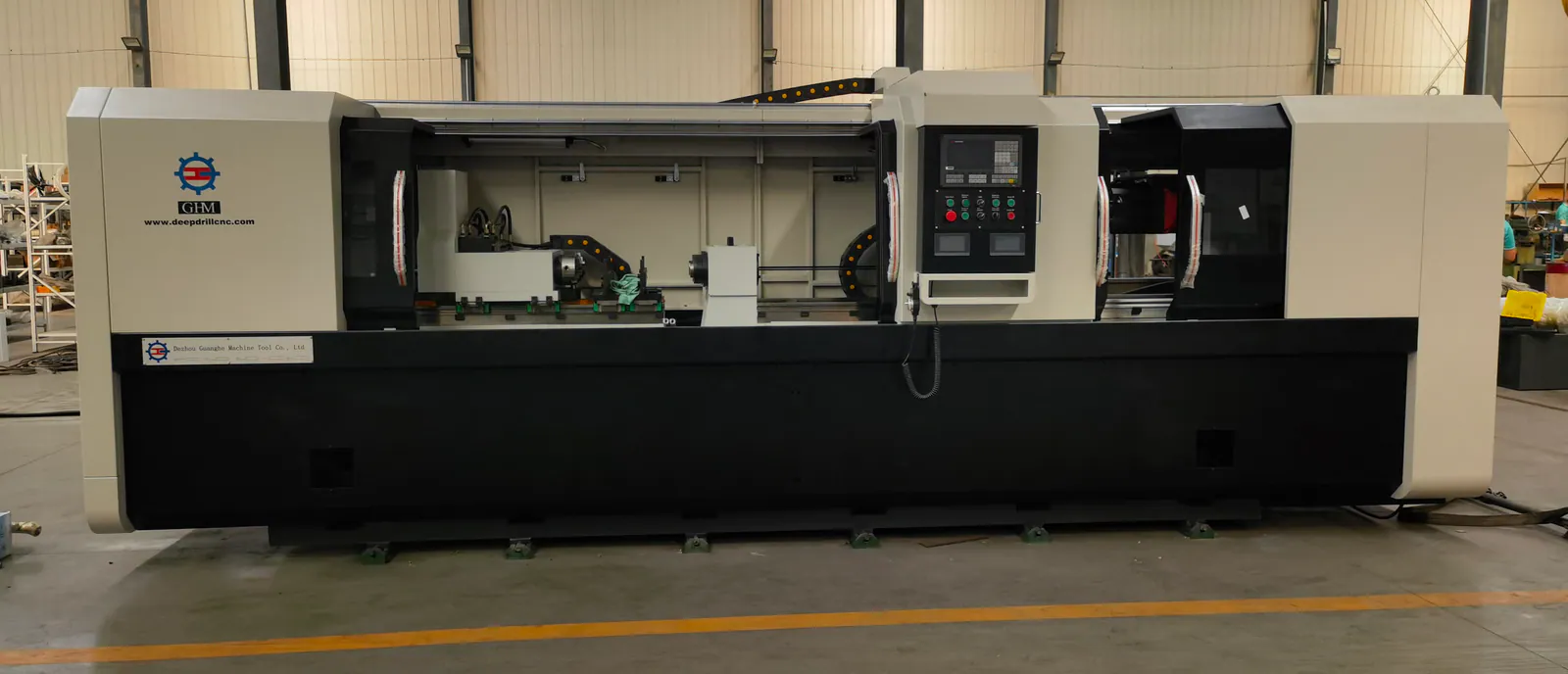
Enclosed machine with work zone open
Open work-zone view for reviewing the spindle, supports, guarding and service access.
Skiving and roller burnishing
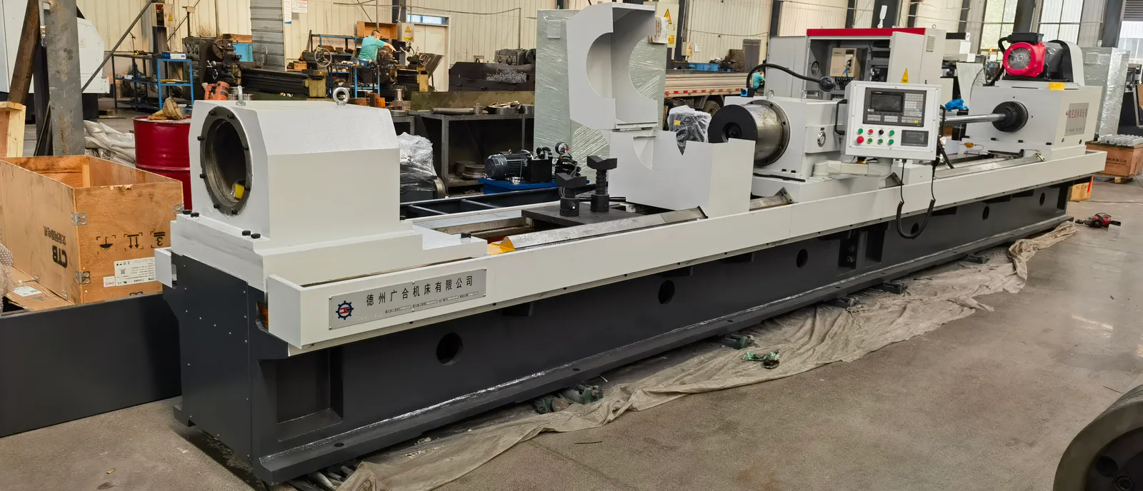
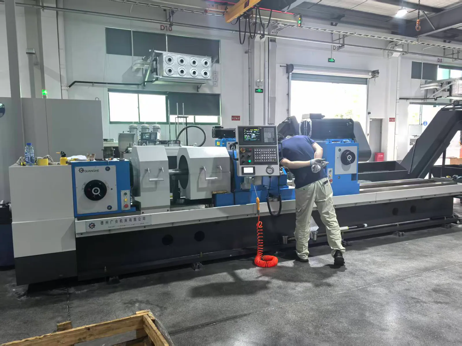
Skiving and roller burnishing machine in assembly
Open-layout machine in the Guanghe workshop. Workpiece support, headstock and control positions are visible.
Skiving and roller burnishing
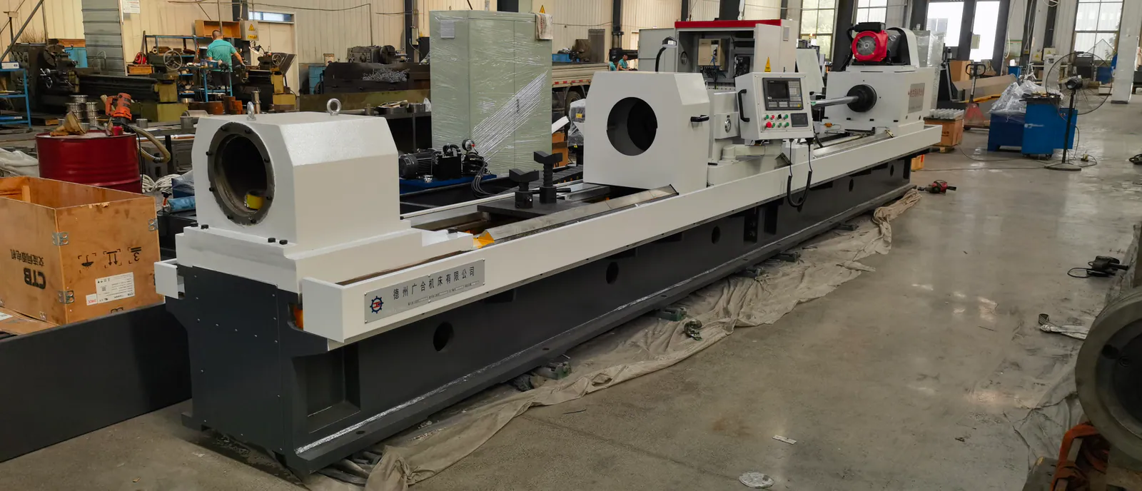
Skiving and roller burnishing machine, rear view
Rear-side view showing the long-bed arrangement and enclosed drive cabinet.
Skiving and roller burnishing
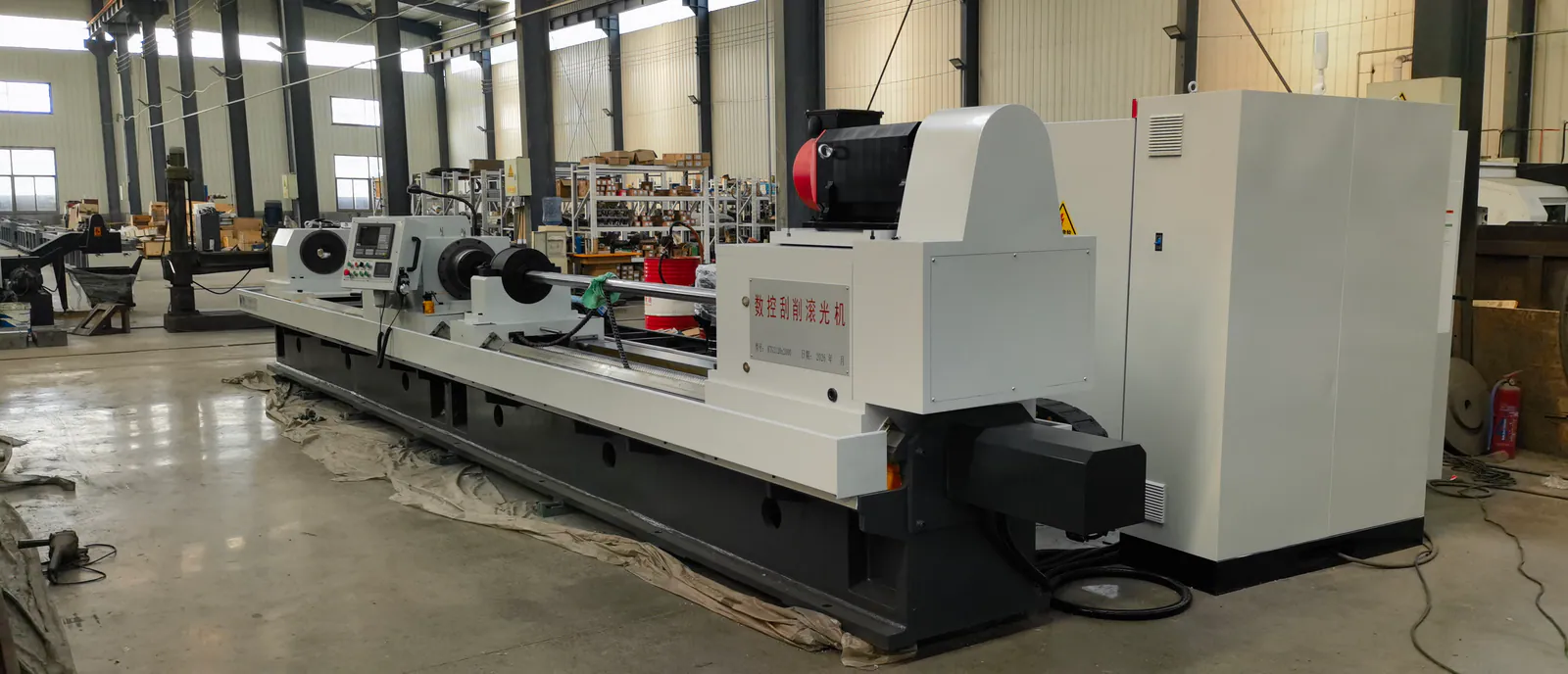
Skiving and roller burnishing machine, front view
A second verified workshop angle retained because it reveals the tool-side arrangement and machine nameplate.
Factory build
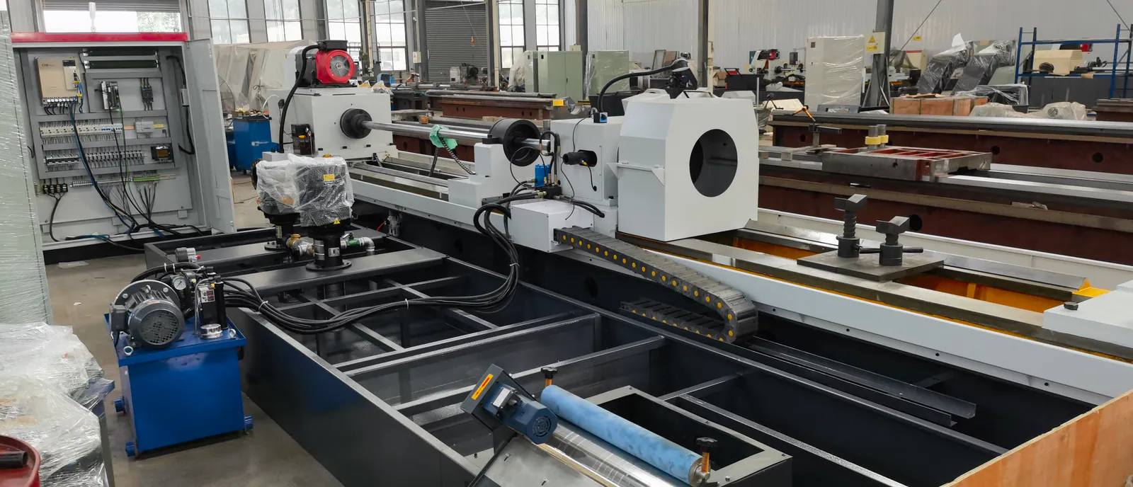
Coolant and hydraulic assembly area
Assembly-stage view of pumps, hoses, cable carrier and machine support structures.
Factory build
Custom deep-hole machine in the workshop
Custom machine layout photographed during the build stage; the exact process and acceptance range are project-specific.
Exhibition
Machine demonstration at an industry exhibition
A machine demonstration image from an exhibition setting. The photograph does not by itself establish customer acceptance or machining performance.
Machine configuration
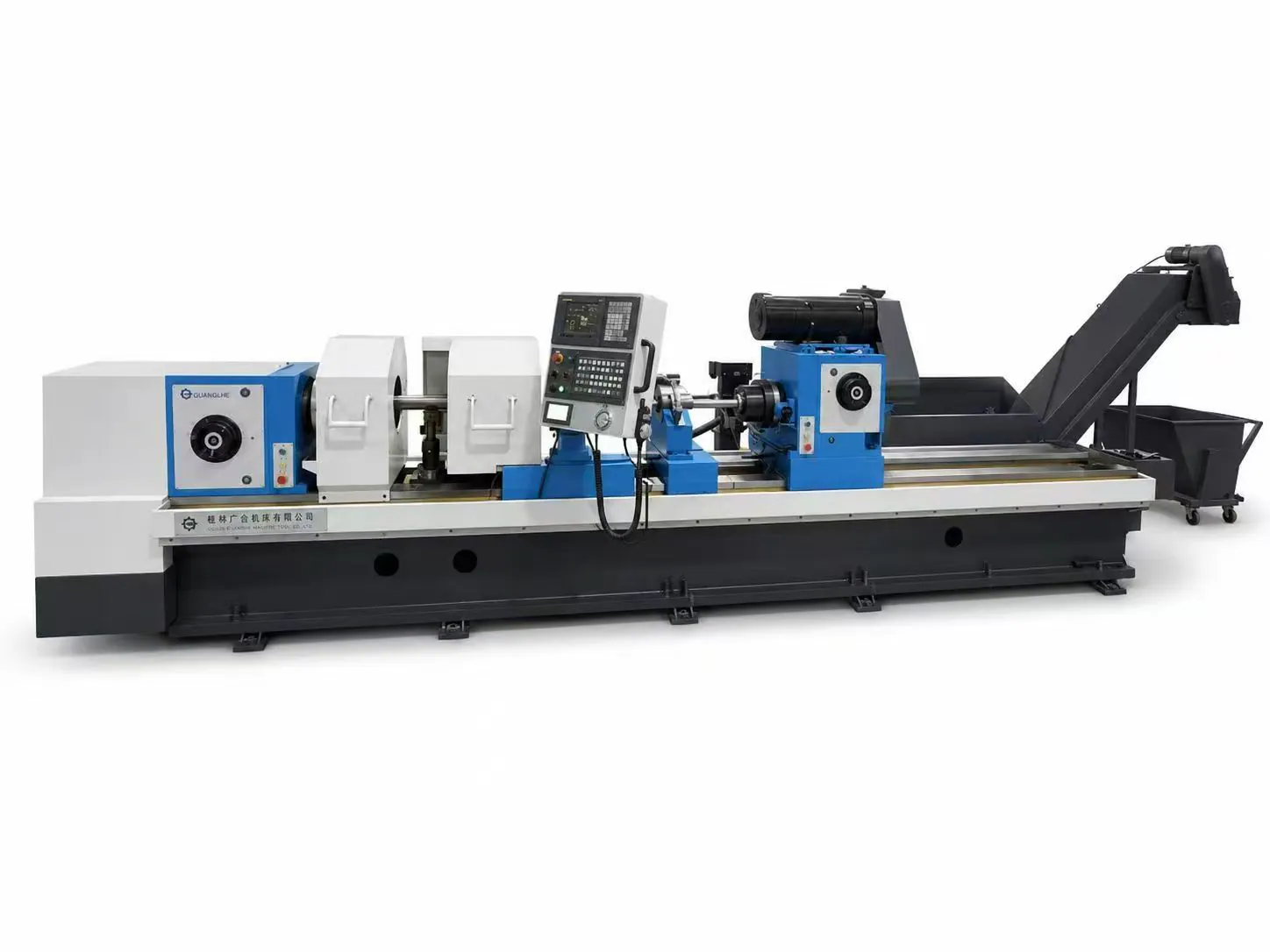
Open-layout deep-hole machine configuration
Open-layout machine image used to discuss bed length, workpiece support and chip-handling configuration.
How to Use These Materials in a Technical Review
Use visuals to compare layouts
Review enclosure, spindle count, workpiece support, control access, coolant equipment, chip collection and maintenance space.
Do not select from appearance alone
Machine type and configuration still depend on material, starting bore, diameter, depth, tolerance, roughness, quantity and takt time.
Ask for linked inspection evidence
A visible bore surface is not a measurement. Geometry, roughness and cycle time require an agreed sample, instrument and inspection record.
Protect customer confidentiality
Identifiable visitor and customer photographs are not published until permission and the claimed relationship are documented.
Send Your Workpiece Drawing
Provide material, starting bore, diameter, depth, tolerance, roughness, annual quantity and target cycle. Guanghe will match the process route and machine layout to the workpiece.